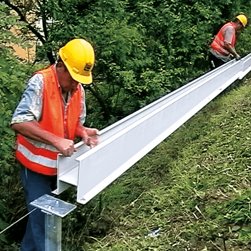
Lid Profile
Installing the Lid
Position and install the lid of 6 m length as follows:
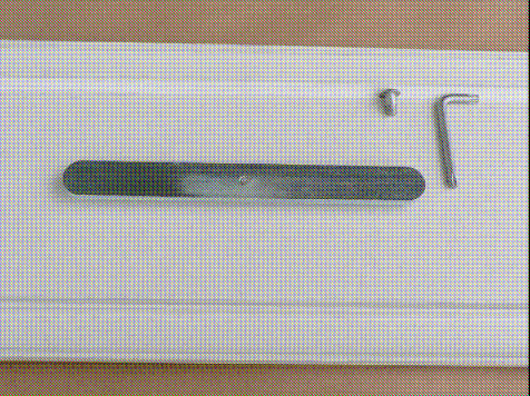
- Insert the bolts (M8x16 with flange), 5 per 6 m of lid profile, into the bore in the lid from the top, and thread 2 turns into the locking bar steadied from underneath (exploded view).
- Rotate the locking bar in the longitudinal direction of the lid (fig. 5).
- On a straight cable trough run, position the first lid so that the lid center is aligned with the joint of the cable troughs (one lid connects two troughs).
- Tighten the bolts using a TX40-headed screwdriver, Allen key, or suitable device. Turning the mushroom head bolt will rotate the locking bar to mesh with the lower part of the cable trough (fig. 6).
- The remaining lids follow the same sequence. For the ends, use a half-lid segment to close the remaining trough sections at the beginning and end of the cable route.
In some bends, the lid may be positioned no further than 50 mm away from the joint of the cable troughs to ensure stress-free installation. The lid must be mitred if there is any change in the direction of the cable duct system.
Note: A 3 mm air gap between lids is required.
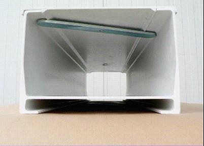 Locking Bar Installed
Do not store the lids loosely and unprotected next to the installed cable duct system. To ensure the stability of the cable duct system, always close the cable ducts with the lids. This prevents incidents during adverse weather conditions.
Note:
The 1A Type has a different fixing arrangement where the duct is bolted to the mounting base plates.